


An emergency stop button is one of the most important safety devices on an autonomous forklift. However, pressing the button and measuring how quickly the vehicle stops are not the same as proving that the emergency stop function is effective.
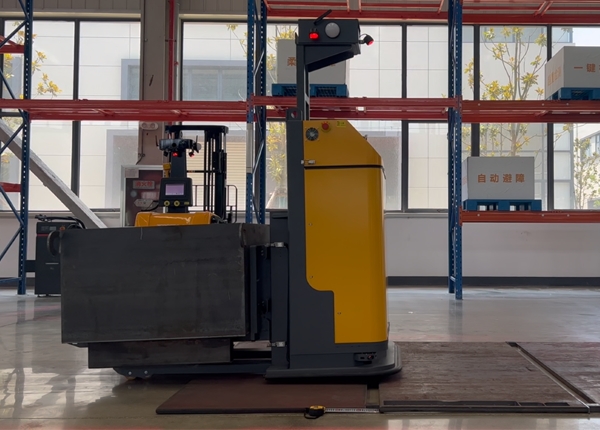
For a Chinese AGV or AMR forklift, the complete emergency stop response may involve the button, safety circuit, safety controller, motor drives, braking system, hydraulic functions, and software-controlled motion. A proper acceptance test must evaluate the complete safety function rather than only the electrical signal.
The exact stopping distance depends on vehicle speed, payload, floor condition, slope, tire condition, braking configuration, and the point at which the emergency stop is activated. Therefore, there is no universal stopping distance that applies to every imported Chinese AGV.
Emergency stop performance should be evaluated using several separate measurements:
Button response time: The time between pressing the emergency stop button and the safety circuit recognizing the command.
Control response time: The time required for the safety controller or related control system to initiate the required stopping action.
Drive response time: The time required for the motor drives to remove or control the propulsion torque.
Mechanical braking time: The time required for the vehicle to decelerate and stop.
Total stopping time: The complete time from emergency-stop activation to zero vehicle movement.
Stopping distance: The distance traveled from emergency-stop activation until the vehicle has stopped.
A vehicle may have a fast electrical response but still require a longer distance to stop because it is traveling quickly or carrying a heavy load. Conversely, a low-speed test with no load may produce a short stopping distance that does not represent the real warehouse operating condition.
The answer must come from a project-specific test, not from a generic specification such as “the AGV stops immediately.”
Stopping distance can be affected by:
Initial travel speed
Vehicle mass
Payload and load center
Floor friction and surface contamination
Floor slope and unevenness
Tire wear and tire material
Drive and brake configuration
Battery voltage and drive condition
Emergency-stop activation method
Whether the vehicle is traveling forward, backward, or turning
For procurement purposes, ask the supplier to provide stopping-distance results at several representative operating speeds and payload conditions. The test should also identify whether the measurement starts when the button is physically pressed, when the safety circuit changes state, or when the drive begins deceleration.
These starting points are not interchangeable. If the supplier reports only the mechanical braking distance, the result may exclude the electrical and control-system delay that occurs before braking begins.
A practical test should use a repeatable setup and an independent measurement method wherever possible.
The test area should be clear of pedestrians, other vehicles, loose materials, and obstacles. The floor condition, travel direction, payload, and initial speed should be recorded before each test.
The test should not be performed in an active warehouse aisle where an unexpected stop could create a secondary collision or load hazard.
The test record should include:
AGV model and serial number
Software and safety-controller version
Battery state
Payload and load center
Travel direction
Initial speed
Floor type and condition
Emergency-stop device being tested
Ambient temperature, if relevant
Number of repeated tests
The preferred method is to use synchronized measurement signals, such as a safety-circuit status signal and an independent motion measurement. Depending on the vehicle design, the test may use a data logger, encoder feedback, a measurement wheel, video analysis, or another validated method.
The measurement system should clearly identify:
The instant the emergency-stop command is activated
The instant the safety circuit recognizes the command
The instant propulsion torque is removed or controlled
The beginning of deceleration
The instant the vehicle reaches zero movement
A simple video recording may be useful for documenting the test, but it may not provide sufficient time resolution for a precise response-time measurement unless the camera and analysis method are suitable for the required accuracy.
One successful stop does not establish reliable emergency-stop performance. Repeat the test under the same conditions and compare the results. If the stopping distance varies significantly, investigate the cause rather than reporting only the shortest result.
Additional tests should be performed at different speeds and with representative loads. A high-lift forklift may also require special consideration because the load position and mast configuration can affect the consequences of sudden deceleration.
Not necessarily. The emergency-stop function must be evaluated according to the actual safety design of the vehicle.
Some AGVs may remove propulsion torque through the motor-drive safety function while applying a controlled or mechanical stop. Hydraulic lifting functions may be handled through a separate safety circuit, hydraulic valve, contactor, or control strategy.
The phrase “power is cut” is therefore too vague. It may refer to:
Removal of motor torque
Disconnection of the drive power supply
Application of a mechanical brake
Stopping hydraulic pump operation
Closing a hydraulic valve
Preventing further lifting or lowering commands
Disabling automatic task execution
These functions may not occur in exactly the same way or at exactly the same time. The buyer should ask the supplier to provide a safety-function description showing what happens to travel, steering, lifting, lowering, forks, and other potentially hazardous movements after an emergency-stop activation.
An emergency stop should also not be confused with normal software stopping. A normal stop may allow the vehicle to complete a controlled deceleration or task transition. An emergency stop is intended to bring the machine to a safe state when a hazardous situation requires immediate intervention.
A wireless emergency-stop system should not be tested only by checking whether the remote control can communicate with the AGV. The important question is whether the emergency-stop safety function remains reliable throughout the required operating area.
A wireless test should include:
Maximum intended operating distance
Obstructions such as racks, walls, columns, and doors
Different warehouse zones
Normal Wi-Fi and radio traffic
Low battery conditions of the remote device
Temporary communication interference
Loss of signal
Remote-control restart
AGV power-cycle recovery
Emergency-stop reset and restart behavior
The test should verify what happens when the wireless connection is interrupted. A safety-related wireless system should have a defined response to communication loss. It should not depend on the operator continuously transmitting a normal command without a documented failure-response strategy.
The buyer should also confirm whether the wireless emergency stop is a safety-rated function or merely a software command sent through the fleet-management network. These are not automatically equivalent.
A physical emergency-stop button may be connected to a dual-channel safety circuit, but the presence of two wires or a red mushroom button does not prove that the complete system is dual-channel compliant.
The complete safety architecture may include:
Emergency-stop button contacts
Two independent signal channels
Safety relay or safety controller
Monitoring of contact faults
Reset logic
Drive or actuator safety inputs
Contactor or brake control
Feedback monitoring
Protection against unexpected restart
A dual-channel circuit is intended to improve fault detection and reduce the likelihood that one wiring or contact failure will prevent the emergency-stop function from operating as intended. However, the safety performance depends on the entire circuit and its validated design.
Ask the supplier for the actual wiring diagram, safety component model numbers, safety-controller information, diagnostic behavior, reset procedure, and relevant validation documentation. Do not accept “dual-channel” as a sufficient technical description by itself.
Resetting an emergency-stop button should not automatically cause the AGV to resume travel or restart a lifting operation.
A properly defined restart sequence may require:
Confirming that the emergency condition has been removed
Releasing or resetting the emergency-stop device
Checking that the safety circuit is healthy
Confirming that the operating area is clear
Re-establishing operator or supervisor authorization
Manually restarting the vehicle or task
Verifying the vehicle state before motion resumes
The exact sequence depends on the system design, but automatic restart after an emergency stop should not be assumed. This is especially important for vehicles carrying elevated loads or operating near pedestrians.
Factory Acceptance Testing should verify both the physical emergency-stop buttons and the complete vehicle response.
A practical FAT checklist may include:
Test every physical emergency-stop button
Test the remote emergency-stop device, if supplied
Test emergency stop during forward travel
Test emergency stop during reverse travel
Test emergency stop while turning
Test emergency stop with representative payloads
Test emergency stop during lifting or lowering, where applicable
Record response time and stopping distance
Verify that the vehicle does not automatically restart
Verify the fault indication in the vehicle interface
Verify the event record in the fleet-management software
Verify the reset and recovery procedure
Verify behavior after communication loss
Verify that safety faults cannot be bypassed through ordinary software commands
The FAT report should identify the test conditions, measurement method, acceptance criteria, measured results, deviations, corrective actions, and retest results. A statement such as “E-stop tested successfully” is not enough for a serious warehouse automation project.
The RFQ should require the supplier to explain the emergency-stop function in technical terms.
Which safety standard and design principles are used for the emergency-stop function?
What is the complete safety circuit architecture?
Are the physical E-stop buttons dual-channel?
Which safety relay or safety controller is installed?
How are contact faults detected?
What happens to the drive motors after E-stop activation?
What happens to hydraulic lifting and lowering functions?
Is the stopping action controlled, mechanically braked, or power-disconnected?
What are the measured response time and stopping distance?
Under which speed, payload, and floor conditions were the measurements taken?
What happens if the wireless emergency-stop signal is lost?
What is the tested wireless operating range inside the warehouse?
Does resetting the E-stop permit automatic restart?
Can the emergency-stop function be bypassed through software?
What safety documentation and validation records will be delivered?
How will the emergency-stop function be tested during FAT and SAT?
The most useful emergency-stop specification is not simply “the AGV stops immediately.” It is a measurable requirement that defines the complete response from emergency-stop activation to the safe state of the vehicle.
For a Chinese AGV fleet, the buyer should require documented stopping performance, verified safety-circuit behavior, defined hydraulic and drive responses, wireless fault handling, controlled reset logic, and repeatable FAT/SAT testing.
This approach makes it possible to compare suppliers on actual safety performance rather than on vague claims about instant stopping or dual-channel emergency-stop buttons.







 Chinese
 English